Ceiling Rose Wiring
The wiring, connecting, installation, fitting or removal of a light fitting should only be carried out by a competent person such as an electrician, one of the reasons being is a safe isolation procedure must first be followed to ensure the circuit has been correctly isolated and locked off.
Lighting Ceiling Rose Wiring
Lighting ceiling rose circuits can be wired in various different ways, in older buildings the “3 plate loop-in” wiring method at the ceiling rose was used (and still is), in newer houses the “3 plate loop-in” wiring method at the light switch is generally employed.
The 3 Plate “ceiling rose” wiring method is were the “loop” (live in and live out) are both taken to each ceiling rose, then a switch wire is taken from the ceiling rose down to the light switch.
The 3 Plate “switch” wiring method is where the “loop” (live in and live out) are taken to each light switch, then a switch wire is taken from the light switch up to the ceiling rose or light fitting.
There are a few variations to the above where a light switch may control more than one light fitting, or a light fitting is switched from more than 1 light switch, there are also a few other scenarios which may differ from the examples above.
Lighting Pendants and Batten Holders
The electrical wiring connections for a Pendant light fitting or a Batten Holder light fitting are basically the same, you will notice that the base of these light fittings are almost identical.
For the wiring and connecting of light switches see How to Wire a Light Switch.
It is not necessary to identify which Feed (Supply) lighting cable is the Feed In and Feed Out as these two cables connect together.
If a 2nd light fitting is connected to and switched by the first light fitting then the wiring connections are different, the connections for the 2nd light fitting are the same as the Lamp Holder connections.
Lighting Ceiling Rose Wiring
The two lighting wiring diagrams below demonstrate the 3 plate wiring method at the light fitting electrical connections for the old red & black wiring colours, and the newer brown and blue wiring colours.
Ceiling Rose Wiring Diagrams

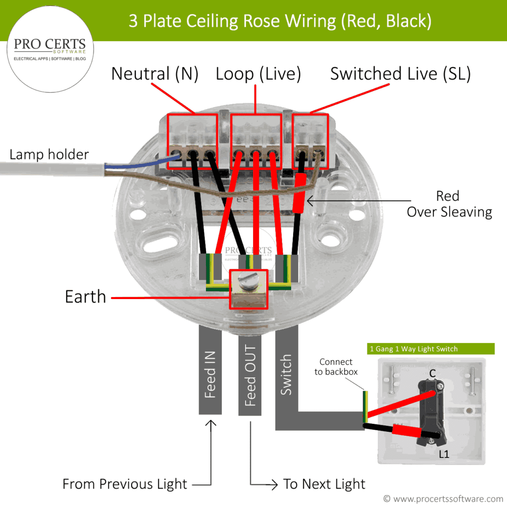
The Feed IN (or live in) wire will be from a previous light fitting, for example a light fitting in another room, or directly from the consumer unit if it is the first light on the lighting circuit.
The Feed OUT (or live out) wire will continue on to the next light fitting.
The Switch wire will be from the light switch to the lighting fitting, this wire contains a “live” core and a “switched live” core. The live core is a permanent live supply to the light switch. When the light switch is turned on the “Switched Live” will become live and energise the lamp (light bulb).
Light fittings with only one cable

In new buildings such as new build houses the ceiling rose or light fitting is likely to have only one cable, this is where the 3 plate at the “Switch” wiring method has been used.
The benefit of this method is that its much easier to replace the light fitting as there is only 1 cable to connect.
This lighting wiring diagram shows the likely electrical wiring for light fittings in new properties where there is only one cable.
Which wire is the light switch wire
In some electrical installations the cable which goes to the light switch might be wired in a twin red or twin brown cable, this is where two of the cores (conductors) are both the same colour, being both brown or both red.
If you are unable to identify which wire goes to the light switch then you will need to test it with a multimeter, set the meter to the continuity (Ω) setting, some multimeters also have an audible buzzer.
To test the switch wire connect the black lead of the multimeter to the blue wire (or black if old colours), then connect the multimeter red lead to the brown wire (or red if old colours) of the same cable.
Now switch the light switch on and off, the multimeter should buzz (if the meter has a buzz function) and will show an ohms reading when the light switch is in the ON position, and will stop buzzing and show an open circuit reading “OL” when the light switch is in the OFF position, some multimeters may show a different value for open circuits.
Follow the above procedure for each cable until you have identified which cable is the light switch cable.
Note, before conducting any tests you must follow the safe isolation procedure.
Lighting Faults
If after you have replaced a new light fitting and the light flickers, that would suggest there is a wiring issue, for help diagnosing this issue see this guide, lights flickering.