RJ45 Connections
An RJ45 plug is used for connecting to Cat5, Cat5e and Cat6 data cables. As shown in the RJ45 wiring diagrams below, the three commonly used Pinout configurations for connecting RJ45 plugs are T-568A, T-568B and Crossover.
The most commonly used RJ45 Pinout connection is T-568B, this is generally used for standard data connections, such as from your internet router to your PC, structured data cabling, a standard patch cable, CCTV cameras and Ethernet cables.
Standard internet connections generally follow the T-568B configuration.
How to connect an RJ45 Plug
Connecting an RJ45 plug need not be difficult, follow the steps below for a simple and easy to follow guide on how to fit and connect an RJ45 plug.
To start with we need the right tools for job. Having the correct tools for the task in hand makes it a lot easier to complete.

RJ45 Connection Tool Kit
- Ethernet cable stripper
- RJ45 crimping tool
- Ethernet cable tester
- RJ45 plugs
- RJ45 boots
- Wire cutters
Method:
- Remove the outer insulation from the Ethernet cable using the cable stripper, being careful not to damage the inner cores.
- Untwist the cable pairs and straighten them out.
- Reorder the inner cores to match the order of the required configuration (T-568A or T-568B).
- Ensure all cores are straight and in the correct order.
- Slide the RJ45 plug over the ethernet cable.
- Check all of the cores are protruding out of the other end of the RJ45 plug.
- Ensure the outer insulation of the ethernet cable is pushed up into the RJ45 plug.
- Check the inner cores are still in the required order.
- Crimp on the RJ45 plug using the RJ45 crimping tool.
- Check the RJ45 connections are mechanically sound and secure.
- Test the cable with the Ethernet cable tester.
Note, screened/shielded ethernet cables require shielded pass through RJ45 plugs. The pass through plugs are easier to fit and connect than the standard RJ45 plugs.
T-568A RJ45 Pinout
RJ45 wiring pinout for a T-568A configuration.
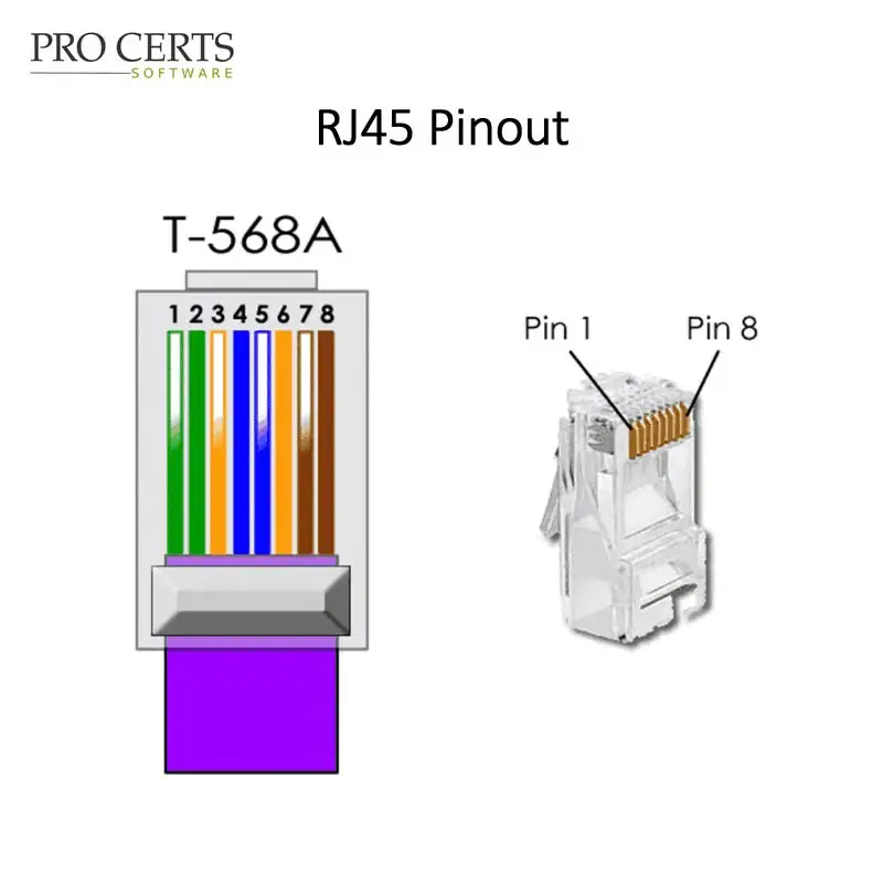
Pin Number | Wire Colour
- White/green
- Green
- White/orange
- Blue
- White/Blue
- Orange
- White/brown
- Brown
T-568B RJ45 Pinout
RJ45 wiring pinout for a T-568B configuration.
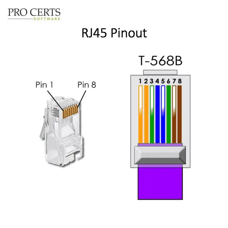
Pin Number | Wire Colour
- White/orange
- Orange
- White/green
- Blue
- White/blue
- Green
- White/brown
- Brown
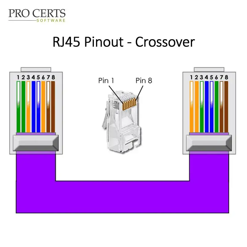
RJ45 Crossover Pinout
RJ45 wiring pinout for crossover cables.
The RJ45 connections for a Crossover Ethernet cable are a combination of T-568A and T-568B, one end (plug) is terminated using the T-568A configuration, and the other end (plug) is terminated using the T-568B configuration, hence “Crossover”.
A Crossover cable is generally used for connecting two computers together, i.e. a direct connection from one PC to another PC.
RJ45 Data Speeds
For data speeds of up to 100Mb only 4 of the 8 cores of the Ethernet cable are utilised (pins 1,2,3 & 6), however pins 4 & 5 are utilised for POE (Power Over Ethernet) equipment.
For speeds of up to 1Gb all of the 8 cores are utilised.
Download The App!
Electrical Tools & Reference, full to the brim with tables, charts, forms and calculators.


For further information visit The Electricians App.
Or, get the cloud desktop version →